LGB UP 2-4-0 Decoder Fitting Guide
Introduction
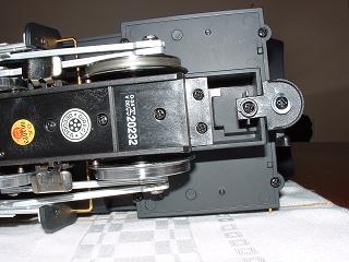
For the second of our tutorial fitting guides, the small american 2-4-0 loco was chosen. This loco has been availible in several liveries over the years, and the current ones include the one of the Union Pacific, code: 20232. This loco I believe is mechanically identical to the 21232, in the Southern livery.NOTE: This loco requires two decoders, one for the loco and an additional one for the tender if you want the sound to work.
If you have read the Stainz fitting guide, you may have been put off fitting your own deocders due to the almost complete dissasembly of the loco required. The 2-4-0 is thankfully much simpler, although some parts are a tight fit. So, lets jump straight in.
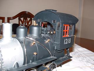
Lets take a look at the loco:

A little dusty i'd admit, but when you are retro-fitting a decoder, a little use is expected!
So, we are going to use LGB's main decoder once again, the 55021 (not the small loco decoder, designed for the field railway locos).

As before, non of the extra bits are actually required, as we have a direct decoder socket to plug the decoder straight into. Personally I keep all the extra bits as you never know when they might come in useful.
Step1: Dissasembly
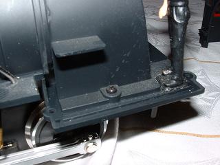
First we are going to remove the cab. There are four retaining screws beneath, (shown below in the four corners). Unscrew these and keep them safe.
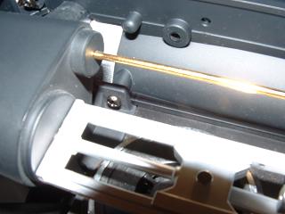
Before we attempt to move the cab, remove the gold rods that come out of the cab, and head to the siver section of the boiler. these simply rotate out of their holes at the silver section, allowing them to be pulled forward to remove them.
The cab will now ease vertically up from the base. The cab curves round the boiler, so naturally provides some resistance, a gentle rocking motion from side to side should loosen it.
With the cab removed, you can clearly see the engineer next to the firebox, containing the selector swtich. There is a screw on each side of the firebox that affixes this piece to the baseplate. Unscrew them both.
To remove the boiler requires a little patience and a small dose of brute force (but not too much!). The boiler is now not permanently attached to the loco, but is held in place by virtue of the selector switch and also a small flap at the base. Easing the top of the boiler backwards will see it clear the switch (it will rub a bit), which then allows it to be pulled towards the rear of the loco and upwards to free it. The engineer shouldn't get in the way too much.

Now to remove the boiler. There are two screws holding the boiler to the chassis at the front, where the main boiler section meets the silver part containing the chimney (smoke-stack i suppose for our American readers.)

As you can see from the above picture, the boiler will now move a short distance vertically. You can also just about make out the lug holding the two parts together right at the top of the boiler. This comes out of the grey section, into the silver part.
The eagle-eyed amoungst you will have notice that the left silver rod has dissappeared. It might be advisable to take these out now. They slot out of the top and then just pull up out of the base.
The boiler can now actually be pulled straight up. Mine was very tightly wedged into the base, so took some gentle persuasion to come out. The main problem is the boiler is circular, with no place to get good purchase on.
Step 2: Fitting the Cab Decoder
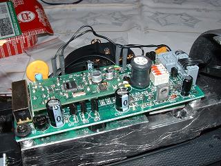
Now we have exposed the circuit board, lets get the decoder in there

Compared to the Stainz board, this one has plenty more capacitors and transistors on it, together with a host of wires; for the smoke generator, lights, and out the back to the socket to connect to the tender.
So, lets get down to business and pop the deocder in. As will all direct decoder installations, the wires on the decoder are not needed. All the power is transferred via the pins on the decoder, through the sockets on the main loco circuit board.
A intial gentle location into the socket, then a firm push down will locate the decoder in place.
The next crucial bit, (you did read the instructions that came with the decoder didn't you?) is to set the DIP switches

They must be set to "OFF", which on our circuit board is towards the front of the loco. Push them all as far as they will go, and then to make sure they are fully there, use a small flathead screwdriver to give them a little extra push.
And there we have it. The loco is complete. At this point i'd highly recommend testing it before re-assembly.
It was at this point that i noticed that the syncronised "chuff" audible from the tender was only idling throught my testing. It turns out this was the battery used for when the loco is stationary under DC power, so it doesn't fall silent. Little did i realise that a second decoder was needed for the tender to have control over the sounds.
Step 3: Fitting the Tender Decoder
The tender has four screws to release the top, easily accessable from beneath.
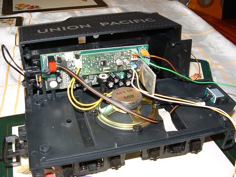
A second decoder drops in the main circuit board here as it does in the loco. Line up the pegs with the sockets and push it home firmly. In the above picture the leads are still on the decoder, but they should be removed before re-assembly. Again, don't forget to set the DIP switches (just right of the decoder in this picture).
Now we have both a loco and a tender fitted with separate decoders. Just a reminder therefore, that you'll have to program them both together when changing the loco number etc.. Otherwise all sorts of funny things might happen. I imagine your "chuffing" will respond to a different loco, most un-prototypical!
You can now re-assemble both the loco and the tender. A word of warning, as with any plastic model, be careful not to strip the threads in the plastic. Just screwing the screws in is a sure fire was to make a big hole out of what should be a nice thread. To avoid this, place the screw in the hole, turn it anti-clockwise (as if you were unscrewing it), until you feel it drop down. This means it is now located at the start of the thread, so you can screw it in gently.

